Stereo buttons - A true story
A while back, the stereo in my friend’s car broke in a particularly annoying way: the “volume down” button stopped working. Or, I should say, it stopped working consistently. Sometimes it made the volume go down. But sometimes it made the volume go up instead, which was truly aggravating if someone annoying like Bruno Mars came on the radio while you were trying to have a serious conversation.
I offered to try and fix it, because I call myself an electrical engineer, and I feel like I should be able do that kind of thing, and also because I like taking stuff apart. Mostly the latter.
This is a story about taking things apart, and putting them back together. It’s full of drama and suspense - no, not really. It’s full of educated guesses and simple experiments, of deduction and doing. I promise to keep the technical material simple enough that you’ll be able to follow if all you know about circuits is the week or two you got in high school physics. Ready?
I popped the front panel module off the stereo, and took it home. My guess was that there was some problem with the button itself, since it was the only thing acting flaky. After removing out four screws and prying gently, I was looking at the circuit board. I pulled it out and began playing with the up button. Perhaps there was something mechanically wrong, so pushing on the “down” side of the switch was actually pushing the “up” button.
Nope. The button and switch mechanism was fine.
I turned my attention to the circuit board. It was remarkably simple. One chip in the middle drove the display, and was connected to about fifteen of the 25 connector pins on the back. This meant that the twenty-odd panel buttons must be sharing the remaining few pins somehow, and there weren’t any other chips on the board that might be doing that job. It was now to use my hard-earned skills as an EE.
I guessed that several switches were mutliplexed onto a single output pin using a series of “voltage dividers”. A voltage divider uses two resistors, like the circuit shown below.
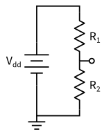
The same current has to flow through both resistors, so if the resistances R1 and R2 are different, the voltages across the resistors will be different (because Ohm’s law says that V=IR).
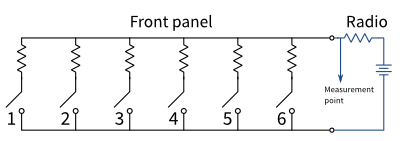
If each switch has a different resistor connected, and there is a device in the radio that can measure the voltage at the indicated point, then it can use that to determine which button is pushed. In my head, I had the circuit below:
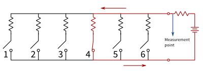
When one of the buttons is pushed, current flows like this:
Then I started probing with a meter to check what the resistances were. With a little trial and error, I found that pushing the buttons labeled “1” through “6” caused a varying resistance to appear between pin 12 on the panel connector and the “ground” pin. I took note of these:
Button  Resistance (ohms)     Function
1       0.5 (short circuit)   Power
2       677                   Volume down (the faulty button)
3       1230                  Volume up
4       1900                  "Loud" (a kind of bass boost)
5       2800                  Display mode switch
6       3980                  --
Indeed, the pins are multiplexed with a set of voltage dividers!
Then I tried pushing buttons 2 and 3 at once, and noticed that the resistance was the same as if just #2 was pressed. I started measuring the resistance between the switches, and quickly had to adjust my mental model:
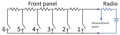
This meant that the actual resistor values were smaller, and they were adding to give the values I was measuring. I found the resistors on the board and measured them, and they matched my expectations:
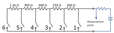
But something about these values looked a little funny. See it?
The resistor values decrease as you go down: 1200, 900, 680, 550. But the last one is 680.
The stereo has trouble telling the difference between when switches 2 and 3 are pushed (volume down and volume up), which would be fixed if the rightmost resistor (the 680 ohm) was a little smaller, and the 550 ohm was a little bigger. In fact, maybe the right one should be 550 ohms, and the 550 ohm should really be 680.
The conclusion was startling, but obvious: the board was manufactured wrong. Someone probably made a mistake loading the reels of resistors into the machine, and made a few hundred incorrect boards. They mostly work, except when humidity or temperature or dirt or the way you push on the button change the resistance ever so slightly and cause them to mistake switch 2 for switch 3.
With this insight, the fix was simple. I pulled out the soldering iron and swapped the two resistors.
And guess what? It worked perfectly!
So what did I learn?
1) Taking stuff apart is fun. (Well, I didn’t learn that. I knew that already.)
1b) Sometimes I can actually fix the stuff I take apart. (Ok, I knew that too.)
2) All that circuit stuff I learned in school is actually useful. People really build circuits like this.
3) The front panels of car steros are really simple. They make them removable as a theft deterrent, but the valuable part is not the front plate; it’s the part you leave in the car.
4) When I fix something like this, I get really excited and want to tell someone. But most people don’t care, so I end up writing unnecessarily long blog posts about it.
Thanks for reading. Now go out and take stuff apart.